Lais are new arrivals on the DCC scene. Based in China, their chips are relatively cheap. I have no knowledge of how well they perform in the long run. I have only just fitted one, but they are cheap enough to not be too worried if they don't perform as expected. I have to say, first impressions are quite good.
Lais can be found here at http://laisdcc.com/
The chip I installed is about the same size as the Gaugemaster chip and harness combination. It is slimmer, but crucially for the Class 47, it is wider. The headroom gained by being a little slimmer is lost as the chip extends almost to the side of the loco. It is very approximately 24mm long, 1.2mm wide and 4mm high. The circuit board on the class 47 is 1.5mm wide.
Unfortunately, the roof will not fit on if the chip is simply laid down on the circuit board. If the circuit board is removed, then a fit is possible, but it is tight. Below are some photos and notes that I made in fitting the LaisDCC chip.
I was fitting this model for a friend who has a sister site at http://www.minitrix.co.uk In fact it was a the relatively rare Queen Mother model. I substituted my own plain grey freight body while I was working on the model. to avoid the risk of getting oily fingers on the paintwork. Oil tends to lift Minitrix paint.
|
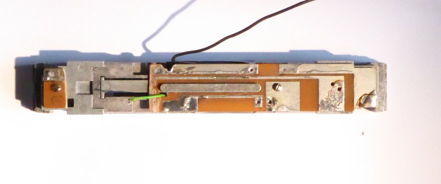
The first jobs are to get the green and wire cables up to the circuit board.
The green cable comes from the pickup on the lower circuit board (and is
+12v). The black wire comes from the -ve feed on the motor, suitably
insulated from the chassis, which it previously pressed against. All
of this is described in the fitting of the Gaugemaster chip. The second thing to do is to cut a chip sized gap in the circuit board - as shown in the photo. Be Careful Here. The board is not symettrical. The two mounting screws are in different places. In the photo, we keep the right hand end as it is so that the mounting screw is retained. This screw connects the circuit board to the chassis. The left hand screw is the one that is going to hold the bulb +12v power supply contact in place. If you chop off the wrong end, there will be no screw to fix the small section. The gap is big enough to allow the chip to rest entirely on the chassis. I have cut a crude notch in the top edge of the board to allow the black wire to pass through to the upper side of the board. |
|
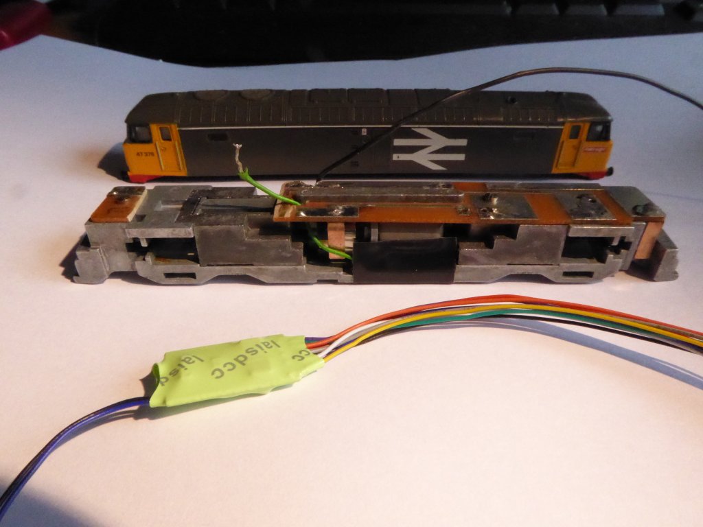
Here is the body, chassis and chip in the same shot. This particular
chip has 11 wires attached to it, only 6 of which I am going to use. The
others are going to get in the way, but the wires have to be handles with
care - their attachment to the chip is only a tiny point of solder.
Not easy to see, but I have put a chamfer on the edge of the circuit board so that the wires from the chip do not have a sharp edge to rub against. |
|
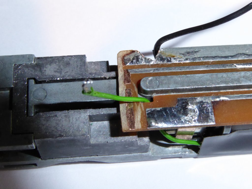
Here's the chamfer that I was talking about. When I put this together, the body did not click into place as it did before I put the wires in. The wires need to avoid crossing the metal bar that protrudes through the circuit board, and need to be laid as flat as possible. A little insulation tape helps. It will come unstuck over time, but once the body is on, that doesn't matter. When clicking the body into place, avoid pressing on the battery box. It is difficult to do, but try ! |
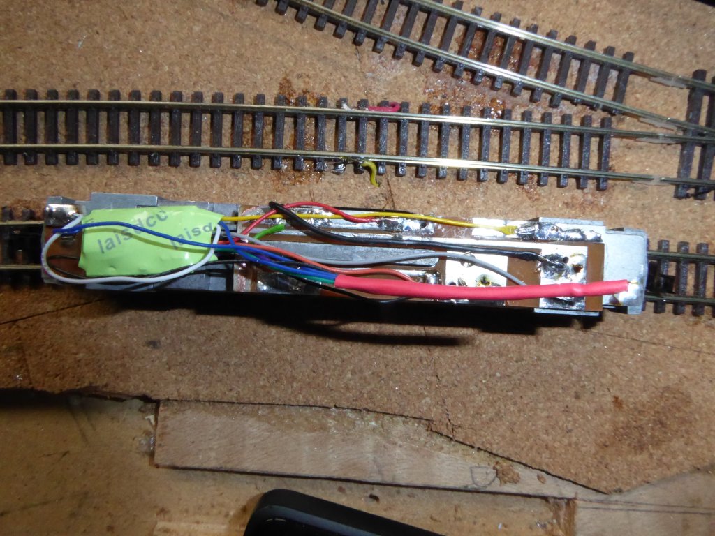
| And here is the chip in its fitted state, with all 6 wires soldered into position, and the green and black feeds from the loco also soldered into place. The spare 5 wires I have cut to slightly different lengths and slipped them inside some red heat shrink tubing, and run the soldering iron shaft down the length to make them a snug fit. The different lengths will prevent the exposed ends of the wires from accidentally touching each other. |
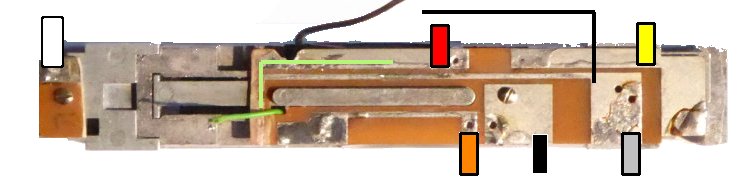 |
The wiring diagram before the wires were attached showing the modified
baseboard from above. Note the small section of the original circuit
board which is retained by the single screw at the left of this photo - this
provides the strip contact for the bulb, and a solder point for white wire
from the chip. It is
slightly different from that used for the Gaugemaster installation, because
some of the conductive tracks have been removed, but the idea of using the
conductive tracks to make the connections remains. Remember - Orange is
Motor +ve (brass tag on circuit board); Grey is Motor -ve (Black lead
recently installed) The green and black wires that we started with are shown as thin coloured lines on the diagram. Don't confuse the black -ve motor lead with the black chip lead. |
Maintaining Classic UK Minitrix Locos
The Minitrix trademark is currently owned by Märklin Inc.
Gebr. Märklin & Cie. GmbH, Stuttgarter Straβe 55-57, D-73033 Göppingen,
Baden-Württemberg
Website ©2002-2018
JFHeath