|
|
The boiler door is the way into the main loco body. It pulls off easily with finger nails. |
|
|
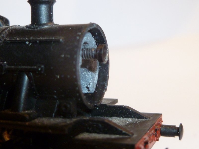
Position of the screw to hold the body in place. |
 |
A video of the process of taking off the body, a manufacturing anomaly, removing the motor and refitting the electrical contact clip. |
|
|
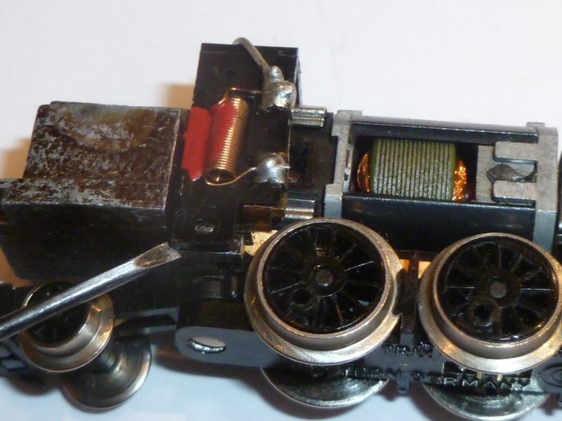
The electrical contact housing. Release the bottom from the clip with a small screwdriver. |
|
|
And here again on the left hand side. |
|
|
The motor is held in place with two spring clips. Do not try to bend these clips - they will break. Use a small screwdriver to lift the bottom of the clip on each side, and then lift straight off. |
|
|
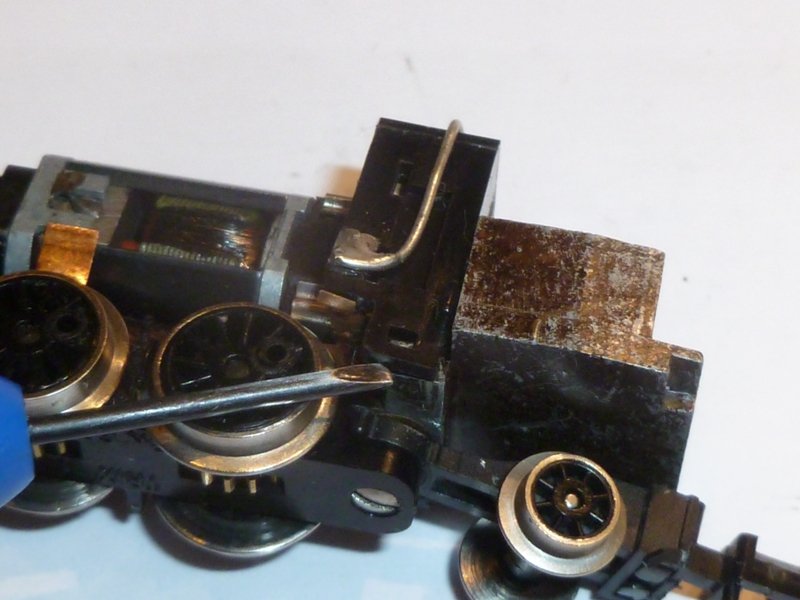
The rear motor clip in position. When removing, the chassi slot provides leverage for a small screwdriver. However, the clip tends to lift one side sooner then the other, and a little help at the bottom of the clip is required. If the clip skews, don't force it. Being spring steel, it will break. |
|
|
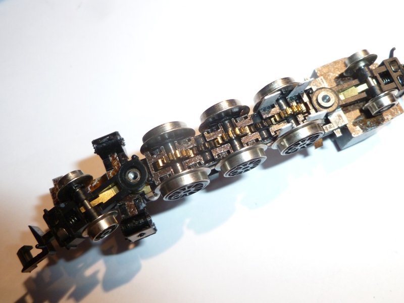
The baseplate is held in with two screws. On removal, a large number of parts become free to fall out. Note the 2 bogies, and their contact strips; 3 main drive axles; 2 smaller gears seated between the drive wheel axles. Note also that as soon as you remove the wheels, the very delicate arms of the contact strip become unprotected. They are easy to catch, bend and damage. |
|
|
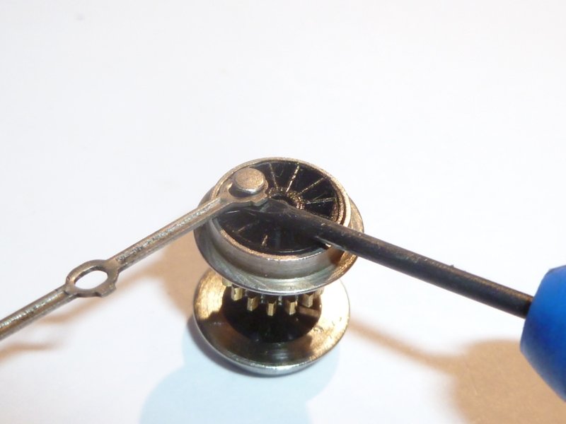
Removing the pins. A gentle prise from under the coupling rod with a fine screwdriver will release the pins. These are metal on this loco. The centre pin holds the con rod which is linked to the valve gear. Probably better to remove the valve gear before the wheels rather than have it flapping around with the chassis not elevated enough to clear the delicate mechanism. |
|
|
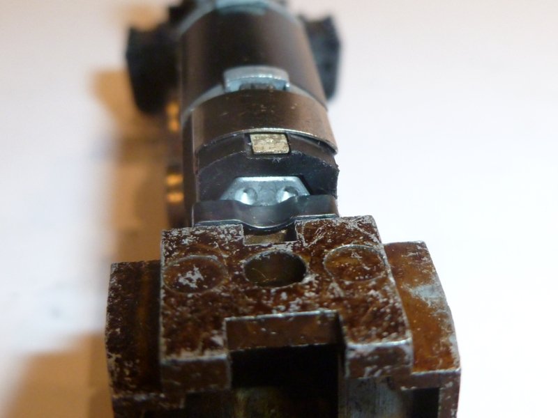
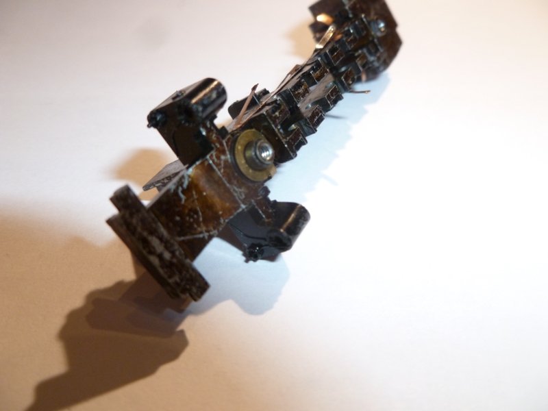
To remove the valve gear you have to remove the gearbox. A fine pointed screwdriver pushed against the pin will force it out of the chassis. The face that you are looking at is plastic - it forms an open box around the metal casing of the gearbox. Once the pin is removed, the gearbox and contact strip will lift straight up. Note that when you do this, a small plastic washer which is under the brass washer on the front bogie position, becomes free. Dont lose it and dont lose the plastic gear from the gearbox! Keep this assembly protected. |
|
|
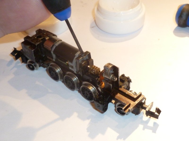
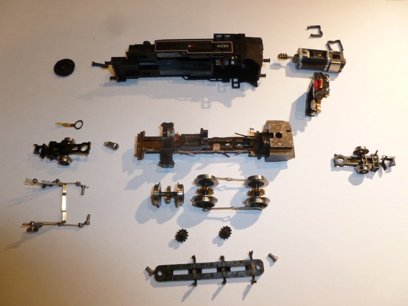
The Ivatt in bits. Well almost. I haven't removed the gear box for this photo. I had already taken off my valve gear - which is shown in the photo, cunningly positioned so that you can't tell that it is broken. |
|
Removing the plastic chassis from the metal chassis. Make sure that the gearbox pin has been removed and turn the chassis upside down so that it rests on the bulb housing and the rear block. The contact washer for the bogies is soldered to the contact strip on the right side of the loco. This needs to be gently eased off its plastic washer, and bent upwards, so that it doesn't get in the way. Don't lose the plastic insulating washer. Note how the plastic moulding dovetails into the metal casting. The plastic chassis has to be lifted rear first. The lugs behind the rear wheel axle slot are captive, and need to be gently prised outwards, away from the chassis, both at the same time, while gently pressing the plastic down towards the table. (If the chassis was the correct way up, we would be lifting the rear of the plastic upwards from the chassis.) The front of the chassis slots in under the metal lampholder upright. Be careful of the brass washer that you bent out of the way, and the whole assembly lifts out. |
|
|
The valve gear comes off with the plastic chassis. In fact, it is possible to remove the valve gear with the plastic chassis raised just a little, and it is probably best to do this to avoid any damage to the fragile components. Note that the piston rod and the con rod on both sides are not permanently connected, and will drop off at some point if you are not aware of this. |
|
|
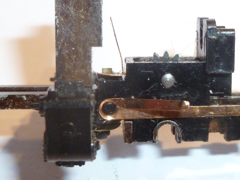
The plastic cylinder mouldings slide out from the side of the chassis on each side. However, there is a little ridge in the metal casting which the plastic cylinders need to be eased over. A very fine screwdriver eased between the plastic and the side arm will help the plastic cylinder moulding to pop off easily. (See photo, and note the opposite side where the cyliners have been removed, revealing the metal ridge). |

Maintaining Classic UK Minitrix Locos
The Minitrix trademark is currently owned by Märklin Inc.
Gebr. Märklin & Cie. GmbH, Stuttgarter Straβe 55-57, D-73033 Göppingen,
Baden-Württemberg
Website ©2002-2018
JFHeath